Wednesday, April 30, 2014

Charging and Discharging a Capacitor


Capacitors carry a charge and a potential that vary with time, using Kirchhoff's loop rule we experimented with a circuit to observe how a capacitor charges and discharges and what factors determine why they do.


Here we derived the time constant T (tao) which was equal to 1/R*C ( resistance and capacitance)
This factor was used in relation with the derivation of the loop rule E-iR-q/c=0 solving  for current
 we found that the charge q=Qf(1-e^-t/RC) was the equation for a charging capacitor with the factor T (tao) determining how fast the capacitor charged and discharged.


       Here was our circuit set up , we used a resistor of 3.5 kohm and a emf of 4.5 V. We ran our         capacitor in series to see how it charged and ran the circuit in parallel to see how it discharged.


We used sensors on the capacitor to record the current through and charge on the capacitor as shown below


We used Logger-Pro to display the relationship between the current and the charge on the capacitor once a current was introduced to the circuit, what we observed was as the charge increased on the capacitor the current decreased as a result of the potential between the emf and the capacitor plate decreasing.
 

As a result of this lab we found that initially when the circuit was closed the charge and potential across the capacitor was zero, after a time the charge increased as a result of the current carrying charge to the capacitor, the current decreased as the electric potential decreased.

Monday, April 28, 2014

Capacitors 1


Capacitors are used to store charge and therefore store potential in the electric field between the equal in magnitude but opposite in charged conducting plates. The given equation we are searching for capacitance is C=Q/V

We used foil as our conducting plates and printer paper as our dielectric ( the medium through which our electrostatic field will be transmitted through). We used a voltmeter to calculate the potential difference between the plates.


During this experiment we added paper between the plates to observe how added distance would effect the capacitance given the same dielectric, charge, and area.

We found that the capacitance of a rectangular plate was proportional to area of the plates, the distance between them, and the permittivity of free space or in our scenario the permittivity of the dielectric (printer paper).


Here is our calculations that we plugged into excel to generate a function displaying the inverse relationship to distance that capacitance has.

 Calculating equivalent capacitance of various capacitors in series and in parallel in a circuit analysis is important to understanding how a certain circuit values can be calculated. Capacitors in series add inversely while ones in parallel add directly.

Loop Rule Bread board

 
Using Kirchoff's laws for circuit junctions and  circuit loops, which states for a junction the total  amount of current entering a junction has to equal the total amount coming out, the loop rule uses the  principle of the conservation of energy to calculate the total potential across the circuit loop. We used a bread board and a diagram to build a circuit and test whether it correctly transmitted current properly. 

 
Given a generic circuit containing  resistors and sources of electric motor force (emf) we used Kirchoffs rules to calculate the potential across a resistors as well as current across a resistor. We created equations which we solved using the systems of equations technique.
 

Here we used a emf source in this case a 9 volt battery, varying resistors ( 3.6 kohm, 2 kohm, 2.2 kohm) and voltmeter to create circuit and test the current through the resistor and the potential drop off that occurs internally in a resistor.

During this lab we conducted various experiments to validate Kirchhoff's laws and how they apply to circuits in real life and theoretically given certain components and voltages.

Wednesday, April 16, 2014

Potential Distributions


During this lab we calculated various potentials due to various objects. Starting with a charged ring we used V=k* Sum dq/r for a point a finite distance from the axis of the charged ring. After some calculations we found it to result in k*Q/(x^2+a^2)^2


We had to calculate the potential difference caused by different charge distributions and different locations of our field points where the potential was to be calculated. We used the definition of the potential at a given point a given distance from a given charge distribution.


We used conductive paper, a voltmeter, and DC supply to calculate the potential between to conductive lines of a positive charge and at the opposite end a negative charge. We used the voltmeter to calculate the potential based on various displacements.


Using excel to calculate the potential difference with varying distances


Throughout this lab we verified how the value of potential varied with distance and location of a charge as well as charge distributions.

Monday, April 14, 2014

4.5 V vs 9 V


We were given a quiz to create the dimmest possible lights. We set up our two 9 volt batteries in parallel, which produced less potential energy, and as a result would send less power to the two bulbs. In addition to putting the batteries in parallel we put the bulbs in series which would also draw less power and therefore create the best scenario for a dim circuit.


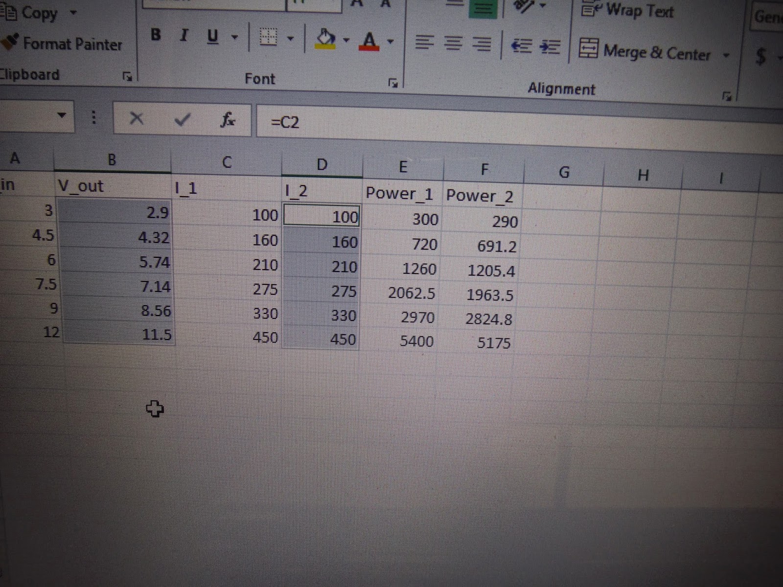
Here is a graphic representation we used to compare the temperature difference caused from the power (P= VI) delivered by  a 9 V and 4.5 V batteries. We used the idea of Q/t for the energy delivered to the water over time. and that the energy delivered would heat the water.


                           Here we used  the 9 V battery to find the heat, power and therefore the temperature difference. After, we used Delta T= Q/mC to calculate the uncertainty in our answer with the known values we were given or found.


Here we did the same calculations as we did for the 9 V battery to find the similar values 


After finding the uncertainties we found percentage of uncertainty, which we found to be 18.65% for the 4.5 V battery and 12.44% for the 9 V battery.

Wednesday, April 9, 2014

Circuits and Current

We  were initially  tasked with figuring out how to light a bulb with various wires and a power source, which we figured out,we also drew a schematic of the loop. Later on, we used the previous activity as a stepping stone to further investigate simple circuits


 We used a electromotive force source (battery) and light bulb ( non-ohmic resistor) to observe the properties and behaviors of a closed circuit as well a its components.


Next, we needed to find an equation that described what caused the closed loop  to light the bulb and how, we derived a relationship between the concentration of particles (n), the drift velocity (vd), which is the motion of a particular particle while it is going through a cross section of a conducting wire in time dt. Also, the area of the material and the charge. We found that these attributes described the current that is present in a conducting wire. The power source used potential as a means to convert energy in the free electrons into the current.


In addition to finding the current and emf, we discussed resistors which caused a drop in voltage (potential)as current passed through them. We observed that the cross sectional area, the length, and the number of loops determined the resistance of the resistor.


Here we used excel to record our data and that of the group of next to us to determine which criteria determined the actual resistance between the two differing resistors each group had.


Towards the end of the day we used a volt meter, which measures potential, a amp meter which measures the current, conductive wires, a power source, and various resistors. We were tasked to  observe the current produced by the power source by means of the ammeter, the potential drop off from the resistors by means of the voltmeter.


Here Eddie is checking the potential difference by placing the instruments on opposites sides of the resistor.

In conclusion, we spent the class time discussing and describing circuits and its components. We found that current I goes through a conductive medium and that as it goes through a resistor the current remains the same but that the energy has a drop off of energy, it then continues on where the emf pumps it back to a high potential and back into the loop.